CRM Boost-PFC circuit
Figure 1 illustrates a schematic diagram of the Boost-PFC circuit in the CRM mode. Figure 2 illustrates the main waveforms of the switching cycle.
CRM mode boost PFC circuit scheme.

CRM Boost-PFC circuit switching…
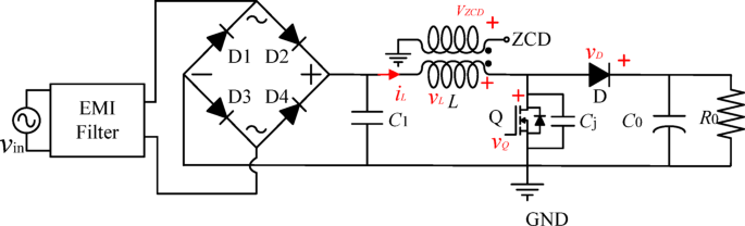
Figure 1 illustrates a schematic diagram of the Boost-PFC circuit in the CRM mode. Figure 2 illustrates the main waveforms of the switching cycle.
CRM mode boost PFC circuit scheme.
CRM Boost-PFC circuit switching…